The UML (Unified Modeling Language) state machine is a powerful tool in the arsenal of software engineers. Understanding it facilitates efficient creation and modification of software systems.
UML State Machine: An Overview
The UML State Machine, also known as a behavioral diagram, is primarily used to handle complex systems.
Basic UML State Diagrams
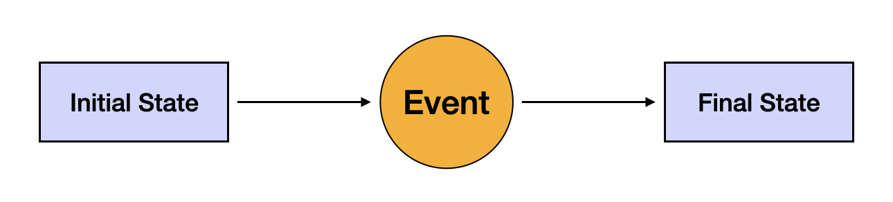
A basic UML state diagram includes states, transitions, and events. A state is represented by a rectangle. Transitions, the shift from one condition to another, are denoted by arrows. An event is something that occurs that can trigger a transition. For instance, a button press can be an event. Here's the illustration:

States can be simple, composite, or substates. A composite state, like a hierarchical state machine, includes other states within it, making them substates.
Basic State Machine Concepts
In any nontrivial state machine, we deal with mechanisms such as transitions, events, and states. Transitions represent the changing of states based on certain conditions (guard expressions) or activities (actions).
An event in a state machine model is an occurrence that may trigger a transition. Events such as the press of a button, a failure event, or the triggering of time-based events like alarms are common behaviors of event-driven objects.
States, in the context of software state, refer to specific stages in a process. A well-defined state represents a point in time that encapsulates the state variables but not the actions being executed.
Behavioral State Machine
In Object-oriented programming, the behavioral state machine is based on the concepts of states, which are distinguished from each other through conditions. This machine is a detailed form of the state machine, providing enhanced semantics for describing complex behaviors within systems.
An instance of the behavioral state machine gives the precise sequence of actions based upon event instances, transitions, and conditions. It specifies the sequences of states an object goes through in response to events that take place.
The behavioral state machine is a crucial part of the UML statechart. It provides mechanisms such as transition, events, and activities to be linked together to form a behavior expression. Transition semantics in the behavioral state machine represent a direct substate and ensure a complete condition by enabling complex conditions and guard expressions.
The execution of entry and exit actions within the internal activities compartment of behavioral state machine governs the process of state changes. These state changes, through the execution of entry and exit actions, result in an active state configuration.
The behavioral diagram in this context provides a high-level view of the state machine diagrams with elements such as pseudostates, amendments to behavior, nodes, and regions. Pseudostates are significant as they allow modeling dynamic behavior.
In conclusion, understanding the UML State Machine allows software engineers to grasp the evolution of complex systems. It is an essential tool for designing and managing dynamic behavior in Object-oriented programming, embedded systems, and event-driven systems. Its understanding allows for hierarchical state nesting, incoming or outgoing transitions, and even powerful semantics for state machines.
Elements of a UML State Machine Diagram
A typical UML state machine diagram contains several key components: entry and exit actions, states and substates, transitions and guard conditions, actions and events, and pseudo-states. Any diagram designed for a software system will incorporate these elements in varying degrees of complexity.
Entry and Exit Actions
In a state machine, each state can specify actions that occur either upon entering the state (entry actions) or upon leaving the state (exit actions). Entry actions are typically used to initiate activities or set variable values during initialization. On the other hand, exit actions are typically used to clean up actions performed during the state or perform necessary actions before moving to a new state, like saving data or cleaning up source code.
States and Substates
States represent specific points in the execution of a system. They illustrate the system's various conditions and operation modes. There are 'simple states', which do not have substates, and 'composite states', which might contain nested substates, allowing for hierarchy within a single state machine. This hierarchical state decomposition provides an ideal mechanism for dealing with complex systems.
Transitions and Guard Conditions
Transitions connect states and signify a change from one state to another, triggered by an event. Each transition has an optional guard condition, usually a Boolean expression that must be true for the transition to occur. If the guard condition isn't met, the transition isn't triggered, and the object stays in its current state.
Actions and Events
Actions are activities that an object may perform while within a state. They can be arbitrary actions like setting a variable, calling an operation, or initiating an action sequence. Events, on the other hand, are occurrences that trigger state changes. They can be external events like user input or internal events like a time-out.
Pseudo-States
Pseudo-states are used to visualize or define default and alternative transitions. These might include initial and final pseudo states (represented by a solid circle and circle surrounding a smaller filled black circle, respectively). Others include choice points to model dynamic decisions (modeled by a diamond) and junction pseudo-states to model a merge between several transitions. This variety of pseudo-states aids in creating well-rounded and understandable UML State Machine diagrams.
In a nutshell, understanding these elements brings us closer to exploiting the full potential of UML State Machine diagrams in object-oriented programming, ultimately enabling the design of efficient and robust software systems.
Creating a UML State Diagram
Creating a UML state diagram is a systematic process that involves identifying the system and its states, drawing the diagram with appropriate notations, and labeling triggering events.
Identify the System and Its States
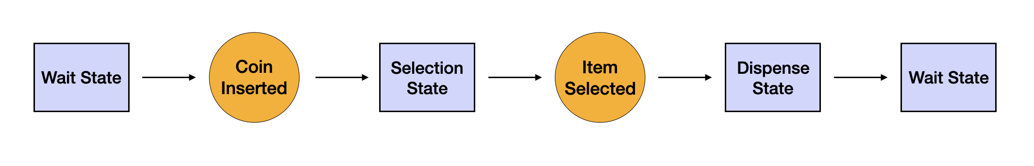
The first step involves understanding the system that the diagram will represent. The system should be an object with distinguishable states. For example, a vending machine is an excellent example of a system. It remains in a wait state until a coin is inserted, then a selection state until an item is picked, and finally an dispense state from where it goes back to the wait state. It could be visualized with the illustration as shown below:
[ Wait State ]--> ( Coin Inserted )--> [ Selection State ]--> (Item Selected)--> [ Dispense State ]--> [ Wait State ]Draw the Diagram with Appropriate Notations
Next, you need to represent the states, transitions, and actions using standard UML notation. Draw rectangles for states and arrows for transitions. Label states and transitions with direct, simple language. Here's how the previously referenced vending machine's transitions would look with illustration:
To summarize, creating a UML state diagram is an essential skill in understanding and documenting systems' behavior. Following these steps will ensure a clear, accurate depiction of a system's activities and state transitions, assisting the software development process.
Use Cases and Examples of UML State Machine
To delve into the practical aspects of the UML State Machine, we'll examine a few examples and use cases in software development.
UML State Diagram Examples
One of the simplest examples of a UML state diagram is a light switch. At any given time, the switch is either in an 'ON' state or an 'OFF' state. The triggering events are the actions of turning the switch either 'ON' or 'OFF'. We visualize the state diagram like this:
[ OFF ] -- "Switch turned on" --> [ ON ]
[ ON ] -- "Switch turned off" --> [ OFF]
This example illustrates a light switch's behavior depicting the two states 'ON' and 'OFF', and transitions triggered by the events -- 'Switch turned on' and 'Switch turned off'.
Application of State Diagrams
State diagrams find diverse applications in software engineering, signaling the dynamic behavior of an object within a system.
For example, consider a simple online ordering system. After a product is added to the cart, the system moves from an 'idle' state to a 'Processing Order' state. Once the payment is confirmed, and the product is shipped, the system shifts to 'Complete Order' state.
Represented in illustration, this could look like:
[ Idle State ] -- "Product Added" --> [ Processing Order ]
[ Processing Order ] -- "Payment Confirmed and Product Shipped" --> [ Complete Order ]
This example provides a more detailed look at how an online order system would handle the process from product selection to order completion.
Case Study: Airport Check-In State Diagram Example
Consider an airport check-in system. Passengers arrive, check-in, pass through security, wait for their flight, and eventually board.
In the illustration:
[ Arrival ] -- "Checks-in" --> [ Check-In ]
[ Check-In ] -- "Passes through Security" --> [ Security Check ]
[ Security Check ] -- "Waits" --> [ Boarding Gate ]
[ Boarding Gate ] -- "Flies" --> [ In Flight ]
This high-level model gives a meaningful representation of the actions and states in an airport check-in system.
These examples illustrate the implementation of a UML State Machine, from simple concepts like a light switch to more complex systems like an airport check-in process. By understanding and applying these models, software engineers can successfully chart complex system behaviors.
Comparison: State Machine Diagram Vs. Flow Chart
While both state machine diagrams and flowcharts are graphical representations used to describe system behavior, they serve different purposes and consist of different components.
Differences between a State Machine Diagram and a Flowchart
A state machine diagram, part of the UML framework, represents the behavior of an individual object as it changes states in response to events. It revolves around states and the transitions between them.
On the other hand, a flowchart breaks down a process into steps showing the order, mechanisms of decision making, and the endpoint of a process. It's typically used to outline an algorithm or a step-by-step process within a system.
The essential difference lies in their focus; while state machine diagrams put an emphasis on 'states' of a system and transitions between them, flowcharts mainly concentrate on the 'flow' of control and the sequence of execution.
In application, you would use a state machine diagram to model the behavior of an object or a whole system, highlighting different states and changes between them. Conversely, a flowchart would be more appropriate for mapping out the workflow or process within that system.
In summary, although state machine diagrams and flowcharts can sometimes seem similar, they are different tools used for various purposes in the design and analysis of systems. Understanding and applying them correctly can make the process of designing complex software much smoother.
Beyond Basic UML State Machines
While we have discussed the basic concepts and elements of UML state machines, more advanced mechanisms like hierarchically nested states, orthogonal regions, the run-to-completion execution model, and the classification of transitions exist that can depict more complex behavior within software systems.
Hierarchically Nested States
UML State Machines introduce the concept of hierarchically nested states to manage complexity. These are states within states, denoting a hierarchy. This system allows the encapsulation of related substates, which can be treated as a single state at the superstate level. It reduces complexity and allows for the reusing of behaviors, which helps in making your model more concise and clear.
Orthogonal Regions
To depict concurrent behavior within a system, UML State Machines uses the concept of orthogonal regions. These are regions within a composite state that can exist in parallel. Each region has its distinct set of states and transitions that can operate simultaneously with the other regions of the composite state. It provides a way to model independent behaviors occurring at the same time within a system.
Run-To-Completion Execution Model
In the run-to-completion execution model, an object processes one event from its event list at a time, during which it runs to completion. The object doesn't interrupt its own processing, ensuring atomic transitions.
Internal and Local versus External Transitions
To offer more granularity, transitions in UML state machines are classified into internal, local, or external.
- Internal transitions occur within a single state and don't result in a state change.
- Local transitions allow a state to transit to one of its direct substates or sibling states without causing exit and entry actions in the higher-level states.
- External transitions make the state machine exit the source state configuration completely before entering the target state configuration.
An understanding and application of these advanced mechanisms will allow you to model intricate concurrent and hierarchical behaviors within your system, facilitating a deeper understanding of the system's dynamic behavior.
Limitations of UML State Machines
Though UML state machines are powerful tools for modeling complex behaviors, they do come with a few limitations.
Firstly, state machines can be hard to manage for intricate systems with multiple states and transitions. As the number of states and transitions increase, the state machine diagrams can become increasingly cluttered and difficult to understand, raising the issue of scalability.
Secondly, state machines capture the behavior of a system but not its structure. They are great for capturing the different states of an object and the events that cause transitions, but they do not illustrate the dependencies between different objects in a system. So, they might not provide a complete picture of the entire system, especially in the context of relationships and interactions amongst multiple objects.
Thirdly, using state machines requires a good understanding of the system's behavior. It's not a tool you can use without a clear picture of the states, events, and transitions that exist in your system.
Despite these limitations, the merits of UML state machines far outweigh their drawbacks, making them an indispensable tool in software engineering, specifically in designing and understanding the behavior of systems. Understanding these limitations can help ideate more concise and effective state machine diagrams.
Key Takeaways
To sum up, UML state machine diagrams are a crucial tool in the field of software engineering, offering a graphical representation of an object's life within a given system. They reinforce the understanding and documentation of the sequence of actions of a system based on various events, states, and transitions.
We learned about the basic elements of these diagrams that include states, substates, transitions, events, actions, and pseudo-states. We further discovered how to create a simple UML state machine diagram from identifying system states to triggering events.
Exploring examples and case studies like a light switch, online ordering system, and airport check-in system allowed us to appreciate its practical application and value. A clear understanding of the difference between state machine diagrams and flowcharts helps in identifying the perfect tool for a given scenario.
The hierarchically nested states, orthogonal regions, run-to-completion model, and varying transition types like internal, local, and external, give this UML tool the power to handle complex hierarchical and concurrent behaviors in systems.
And while useful, UML state machines do come with their set of limitations, including lack of scalability, incomplete representation of a system's structure, and requirement of in-depth understanding for effective usage.
In spite of these limitations, the utility of UML state machines in effectively mapping and designing systems' behaviors stands uncontested. Hence, mastering this tool is paramount for software engineers.
Frequently Asked Questions
One way to consolidate our understanding of UML state machines is to explore some frequently asked questions about its application and functionality.
What Is Event-Driven Behavior in UML State Machine?
Event-driven behavior in a UML state machine primarily refers to the transitions between states in response to various events. These events, triggered internally or externally, cause the state machine to move from one state to another. For instance, in an elevator system, the event of pressing a button to a specific floor would cause a transition from the current floor state to the desired floor state.
What Is the Role of Pseudo-States in UML State Diagram?
Pseudo-states play a crucial role in UML state diagrams as they help in understanding and visualizing the default and alternative transitions. These might include initial and final pseudo states, choice points for modeling decisions dynamically, and junction pseudo states for modeling a merging between several transitions. Therefore, pseudo-states are used to facilitate the depiction of complex control logic in a concise manner.
How Are UML State Machines Used in Real-Time Embedded Frameworks?
In real-time embedded frameworks, UML state machines are utilized to model the dynamic, event-driven behavior of the system. They help in designing the control software and understanding the system's sequential and concurrent operations. The concepts of hierarchical state decomposition and concurrent state handling allow for effective depiction of complex behaviors within the framework. It helps programmers visualize the states, transitions, and events easily, promoting efficient development and maintenance of the software.